Demister Pad / Mist Eliminators for Knock out Drums
Demister Pad / Mist Eliminator for Sour Gas Knock Out Drum
Size: 853 mm Dia. × 150 mm. thickness
Service fluid type: Sour Gas and HC (H2S 14.6 mol% & Aqueous Phase 0.28 mol%)
Particles size: 10 microns.
Material: Stainless Steel 316L
Operating pressure: 71 psig.
Operating temperature: 52 degree C.
Demister Pad for Fuel Gas Compressor Suction Knock Out Drum
Size: 610 mm Dia. × 150 mm thickness
Service fluid type: Sour Gas (H2S=SOR 17.34 mol%, EOR 16.98 mol%, H2O 1.88 mol%)
Particles size: 10 microns.
Material: Stainless Steel 316L
Operating pressure: 23 psig.
Operating temperature: 43 degree C.
Material style:
Knitted Wire Mesh, Density: 9.0 ib/ft3 , Wire Dia.: 0.011 in.
Flow rate of gas, to evaluate the type of mesh.
Sour Gas KO Drum: 8063 lb/hr.
Fuel Gas Compressor Suction KO Drum: 7621 lb/hr.
General Arrangement Drawing for Fuel Gas Compressor Suction Knock-Out Drum:
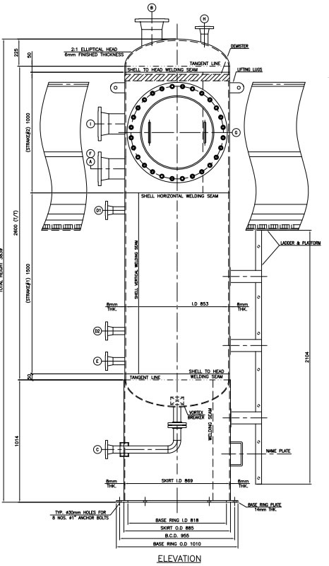
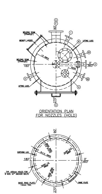
| TABLE OF CONNECTIONS (HOLD) | |||||||||
| MARK NO. | NOMINAL SIZE | QTY. | SERVICE | PRESSURE RATING | PROJECTION OUTSIDE | NOZZLE NECK THK./SCH. | TYPE OF FLANGE | REPAD SIZE O.D x THK. | REMARKS |
| A | 6" | 1 | SOUR GAS INLET | 150# | 200 | SCH.40 | R.F | - | (NOTE—10) |
| B | 6" | 1 | SOUR GAS OUTLET | 150# | 200 | SCH.40 | R.F | - | (NOTE—10) |
| C | 2" | 1 | HYDROCARBON OUTLET | 150# | 150 | SCH.160 | R.F | - | W/VORTEX BREAKER |
| D1/D2 | 2" | 2 | LEVEL CONTROLLER | 300# | 150 | SCH.160 | R.F | - | (NOTE—10) |
| E | 2" | 1 | STEAMOUT | 150# | 150 | SCH.160 | R.F | - | (NOTE—10) |
| F | 6" | 1 | SPARE | 150# | 200 | SCH.40 | R.F | - | (NOTE—10) |
| G | 24" VTC | 1 | MANHOLE | 150# | 250 | - | - | - | (NOTE—10) |
| H | 2" | 1 | VENT | 150# | 150 | SCH.160 | R.F | - | (NOTE-10) |
| I | 6" | 1 | PRESSURE RELIEF VALVE | 150# | 200 | SCH.80 | R.F | - | (NOTE—10) |
Materials
Shell: SA-516 70 KILLED (NACE MR-0101/ISO 17495-1)
Heads:
SA-516 70 KILLED (NACE MR-0101/ISO 17495-1)
Skirt:
ASTM A—283 Gr.C
Welded Fittings:
ASTM A-234 Gr.WPB (NACE MR-0101/ISO 17495-1)
Flanges:
ASTM A-105 (NACE MR-0101/ISO 17495-1)
Nozzle Pipe:
ASTM A—106 Gr.B (NACE MR-0101/ISO 17495-1)
Ladder & Platform:
ASTM A—36 HOT DIPPED GALVANIZED
Gaskets: NON-ASBESTOS
Nuts:
ASTM A-194 Gr,2H
Bolts:
ASTM A-193 Gr.B8/ASTM A-194 8
Anchor Bolts:
ASTM A—36
Internal:
SS 316L
Notes:
1. All dimensions are in mm. Unless otherwise stated.
2. All bolt holes in manways, handholes, nozzles and anchor bolts on support shall straddle the normal vessel centerline.
3. After the final test, the vessel shall be dried & cleaned thoroughly of all grease, loose scale & rust (both, internally and externally).
4. Thicknesses specified are minimum, to be after forming / rolling.
5. All sharp corners shall be rounded off to minimum 3mm radius.
6. All nozzle flanges raised faces will be necessarily serrated.
7. Main vessel weld seams to be located, clear of attachments.
8.
All welds for pressure parts shall be full penetration welds. Chip back to sound metal
and rewelded from the other side. Wherever backing is not possible, root run shall be
tig welded, inside portion of weld to be ground flush for cladding application.
9. Nozzles orientation & elevations to be finalized by the client.
10.
Nozzles shall be self reinforced & integral type.